Custom Dynamics LED Indicators

dynalow

Club Member
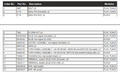
I'm interested in fitting CD's LED front running and turn light inserts to a 2016 Street Glide Special. However, International models, part no PB-AW-1156, aren't plug & play (unlike their U.S. equivalent, 1157) and require a separate power connection for the running light (see attachments). Before I start pulling things apart, has anyone fitted these or is able to recommend the nearest, and tidiest, power pick up point, please?

1678447122872.png

1678447539207.png
 
Check the wiring diagram for your bike. I have a Sportster here and the connector under the tank is a 6 way to support running lights in the indicators but nothing connected to blue wires as not in use.

If I have this correct on a FLHX/S the connector is 31 and is in the fairing.
 
Last edited:
I'm interested in fitting CD's LED front running and turn light inserts to a 2016 Street Glide Special. However, International models, part no PB-AW-1156, aren't plug & play (unlike their U.S. equivalent, 1157) and require a separate power connection for the running light (see attachments). Before I start pulling things apart, has anyone fitted these or is able to recommend the nearest, and tidiest, power pick up point, please?

View attachment 1193468

View attachment 1193469

I’ve fitted a set to a 2017 Street Glide Special, if I remember correctly I took the live feed from the back of the dash mounted 12 volt accessory power supply. Taking the live feed from the pilot/sidelight fitting would work equally as well.
 
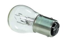
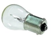
Brief explanation, the US (Domestic) have running lights in the indicators, this is achieved simply by using what we use as a stop tail dual filament lamp, 21/5w the higher wattage as the indicator, the lower as the running light, so their lamp holders have two pins & indicator wiring three leads, Indicator live, running light live & earth.
HDI (UK) only have the single pin light holder, so only two leads, Indicator live & earth.
Screenshot 2023-03-11 164008.jpgScreenshot 2023-03-11 164107.jpg
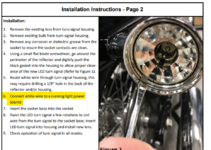
So basically you have to feed the running light live (White lead in kit) through with the existing indicator wiring route to inside the bat wing, to be honest I suspect that will be the hardest part of the job!

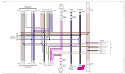
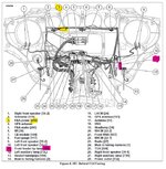
Where to pick up a 'running light' feed as said you could use the P&A power connector, or tap in as Andy in Beds into connector 31, there are a few other options as well.

However, I would suggest one of the best places to take a running light feed live is off the lighting circuit from the connector that is not being used on the Street Glide, the Fender tip light.
The advantages of using this feed over the others are, this is the appropriate to the lighting circuit and the CanBus monitoring of this circuit has the spare capacity not to trip any fault codes due to extra load etc. (unlikely with LEDs) and will function in the accessory position.
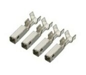
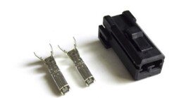
No splicing required, you just need a AMP/TYCO connector & pins. (see below)
Screenshot 2023-03-11 163927.jpgScreenshot 2023-03-11 163345.jpg

AMP/Tyco Multilock (70)
Fender Tip lamp connector [32](& P&A Power [
299] same connector)

H-D part numbers

73152-96BK Socket housing 2-way x 1
73191-96 Socket (connector) x 2
Screenshot 2023-03-11 164728.jpg
 
It already feels like a bodge job having to somehow route that single wire to an appropriate place especially if you take it to anywhere other than where HD intended the running light to go.

Although the cost may seem prohibitive I would see if I could get the domestic market indicator internals that will have the 3 wires in the one sheathing. Failing that the complete indicator.

The commercial part numbers for the pins are
Pin... 173645-1
Socket... 173631-1
Housing part numbers
Pin housing 2-way... 174460-2 Receptacle
Socket housing 2-way... 174463-2 Plug
 
Last edited:
It's not that hard as the wiring is all hidden behind the bracket and then in the Bat wing. It not really practical to change the internals of the indicators as the lamp holders are not held in by fastener but sort of crimped over!
1678557463727.png
 
I know wiring isn't hard which is why I suggested using the point in the wiring loom that HD specifically put there for running lights in the indicators. It is also why I then suggest getting the domestic market indicators and doing the job properly.
 
I know wiring isn't hard which is why I suggested using the point in the wiring loom that HD specifically put there for running lights in the indicators. It is also why I then suggest getting the domestic market indicators and doing the job properly.
You're right, but rather than buy and extra set of indicators, the amount of work is the same to replace them as just run the white wire to the spare position in the indicator connector, as Watchman said the wiring is all there, the connector is the same, you just need the extra terminals!


1678561761270.png

1678561834454.png
 
Make your mind up on where you think that extra wire should be run.

In my first post I told of using connector 31. It just happens to be the one for the indicators.
 
Make your mind up on where you think that extra wire should be run.

In my first post I told of using connector 31. It just happens to be the one for the indicators.
Yes what you first said to 31 where the indicator plugs in, I suspect the sleeve is the same and you could thread the white through it but just run the white to the indicator side of the connector there should be spare way for the terminal for the running lights.
 
This is what I completely forgot, Street Glide front indicators plug in under the mounting bracket outside the Batwing, sorry for the 'Red Herrings', the other methods will all work, but the below are far easier!

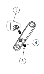
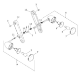
Found some good detail pictures, so basically if you replace the indictors you undo the two outside acorn nuts to remove the bracket and there's the connector [31] and as Andy/Watchman said, pre-wired and where the USA running light is supplied.

One bolt if you need to get the indicator off the bracket.

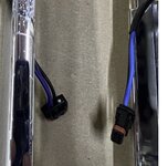
These pictures are a US set with running light, so have the extra Blue wire for the Running light live and as previously said would just plug in and work as indicator & running light.

Screenshot 2023-03-12 073907.jpgScreenshot 2023-03-12 074809.jpgScreenshot 2023-03-12 074711.jpg

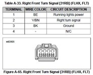
On the UK version there will be no Blue wire, Just the Black Earth & Violet Indicator live, in position 2 & 3 with two white plugs in the ends of the connector in position 1 & 4. (One is visible in the pictures being the USA set up in position 4, the other would be where the Blue wire is position 1)

So if you have the above Customs Dynamics kit you could feed the white wire through, it may fit the in the existing sleeving or your could just run an additional bit of sleeving, buy two JAE MX190 connector terminals, H-D Part 72910-11, one for each side, take the white plug out of terminal position 1, crimp the terminal onto the white wire and install that then into position 1 on the connectors and you have your Running light live feed!


Screenshot 2023-03-12 081544.jpgScreenshot 2023-03-12 083006.jpg
 
Thanks for all the helpful, and informed, comments - the forum at its best. I'll get the CD lights ordered and feedback on progress. Again, thanks.
 
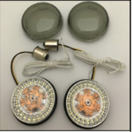
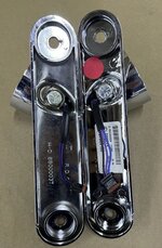
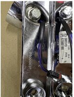
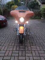
I finally got round to installing the Custom Dynamics indicator/running lights. Thanks to the info posted here, it was a doddle. As advised, I used the P&A socket (299) to provide the live feed - the unused front fender light supply (32) was just as accessible. The only minor issue was seating the LED units into the indicator housings, not helped by the bulky in line resistor in the running light wire (not visible in the product literature). A judicious smear of Vaseline on the housing's rubber insert helped things along nicely and job done. The end result was better than expected. The white LED halos provide a good spread of light up front, and much cheaper than HD's auxiliary light set-up, so, hopefully, less chance of any more 'Sorry I didn't see you' events.
CD Turn Signals.jpg
 
Back
Top