Oil leak after re-assembly

Ex3t3r

Club Member
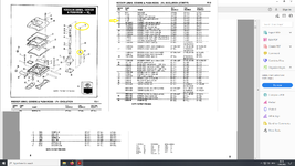
Took barrels and head off for ceramic coating now they are back and fitted an oil leak has now appeared which seems to be coming
from the upper push rod cover that fits inside the bottom of the cylinder head (not 100% sure as its flushing oil) in 'Parts Diagram'
attachment is item 16 (marked in yellow) the rubber seals as indicated in the parts manual - item part # 16 H-D 11157
that fit over the end of the push rod upper cover ?

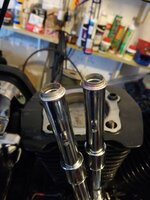
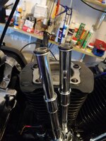
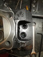
Pic 1 & pic 2 have been posted for reference purposes and pic 3 is the cylinder head flipped upside down with the alleged
rubber seals insitu. The set of push rod covers are after market but were not cheap and the rubber seals are from James,
could it be that the ceramic coating all be it is a very thin fine coating is preventing this rubber seal from doing its job and
the engine oil is passing or am I missing something here during re-assembly?

Would appreciate your comments please guys

Model: 1340 Evo FLHS Year 1991

Ps. Took head off to see if I had missed something but reluctant to reassembly the head to identify the exact source of the leak as this is no 5 minute job
hence my post or maybe you may think I should!?
 

Attachments

  • Parts Diagram.png
    Parts Diagram.png
    679.7 KB · Views: 223
  • Pic_1.jpg
    Pic_1.jpg
    3.6 MB · Views: 195
  • Pic_2.jpg
    Pic_2.jpg
    3.7 MB · Views: 295
  • Pic_3.jpg
    Pic_3.jpg
    3.8 MB · Views: 232
Looking at your pictures it doesn't look like you have dissembled your push rod tubes. This might have caused a location problem. Just pull the top half clip forward on the tube and they will compress. If you do this you can re-assemble with all the tube items in the correct order but un-tensioned then tension the tubes on completion. This also helps you locate the pushrods. Grease the seals so that they don't try to hang up in their location counter bore. HTH
 
Just make sure everything is in place as it should be, you have not pinched that o-ring, it is the CORRECT o-ring, try a new one! .....and that you have the top of the pushrod tube pushed very firmly into position in the head...you can feel it when it goes in right. Don't sweat it...should be pretty easy
 
Looking at your pictures it doesn't look like you have dissembled your push rod tubes. This might have caused a location problem. Just pull the top half clip forward on the tube and they will compress. If you do this you can re-assemble with all the tube items in the correct order but un-tensioned then tension the tubes on completion. This also helps you locate the pushrods. Grease the seals so that they don't try to hang up in their location counter bore. HTH
Simon_A all new pushrod tubes and rubber seals old one's were pitted to hell, just put them loosely together for illustration purposes, I am not sure what you mean when you say 'Just pull the top half clip forward on the tube and they will compress' ?

This is the method I used when re-assembling:
1. Assemble pushrods/ O rings then place on in Tappet guide (the O rings are off different sizes so seems easy to locate correct position espically the one that fits under cylinder head)
2. Offer cylinder head up then torque down in order (ensuring pushrod covers are nicely located first)

Please excuse my ignorance tried to assemble in the same reverse order. I always use assembly grease when carrying out this type of work and the rubber O rings look undamaged so I don't think they have been pinched. Will try again but would you guys recommend Hylomar Universal gasket+jointing compound on the O rings to ensure a better oil tight fit?

Also thank you kiwidave for your valued input as always.

 
There should be no need for a Gasket Sealant on the O Rings. A touch of oil on the top part of the Tube that seats the O Ring should be all that is needed. When you expand the Tube into the Head get a flat blade Screwdriver and push up on the fat part of the Tube just under the O Ring to get it seated into the Head. You will feel a little click when it seats.
HTH. Good luck.
 
1652772588355.png


Referring to the attached drawing which is from an earlier bike but basically the same. The push rod tube comprises of 4 major parts and 3 o rings. If assembled without item 31, part 27 can slide down into 28 . If installed like this the tube can then be extended once the cylinder head is installed by holding 28 on the tappet block and pushing 27 up into the head pocket with a screwdriver. Place clip order the top lip and onto of the spring cup 34......Jobs done. This is the way adjustable pushrods are adjusted once installed and you get to feel the pushrods are seated correctly. HTH
 
View attachment 1189193

Referring to the attached drawing which is from an earlier bike but basically the same. The push rod tube comprises of 4 major parts and 3 o rings. If assembled without item 31, part 27 can slide down into 28 . If installed like this the tube can then be extended once the cylinder head is installed by holding 28 on the tappet block and pushing 27 up into the head pocket with a screwdriver. Place clip order the top lip and onto of the spring cup 34......Jobs done. This is the way adjustable pushrods are adjusted once installed and you get to feel the pushrods are seated correctly. HTH
I see what your are saying now Simon_A, "A picture paints a thousand words" Thank you for taking the time to help and also others too (y)
 
Last edited:
Back
Top